LED Workbench Lighting

Here is a very useful workbench lighting unit for electronics hobbyists. The portable inspection lamp circuit consists of an on-board voltage regulator and a high-bright 5mm white LED. Any 9 to 18 volt dc rated ac mains adaptor, capable to source about 100 mA of output current can be used to power this portable inspection lamp.

After construction the led workbench light circuit should be enclosed in a suitable plastic bottle cap as illustrated here. The miniature lens shown is an optional component. In the prototype, plastic made lens lifted from a discarded torch was used!
Circuit Project: LED workbench lighting

LED workbench lighting lamp circuit schematic
Circuit Project: LED workbench lighting
The adjustable 3-pin voltage regulator IC1 (LM317L) in TO-92 pack, is here tuned to supply an output of near 4.5 volt dc. This supply is directly fed to the white LED (D2) through the current limiter resistor R3 (51 Ohm). Diode D1 (1N4001) works as an input polarity protection guard and two small electrolytic capacitors (C1 and C2) connected at the input and output pins of IC1 improves the overall stability of the regulator circuit. Use a standard RCA or EP socket as the input terminal J1.

Circuit Project: 0.3 to 1.5V LED Flashlight

Circuit Project: 0.3 to 1.5V LED Flashlight

It's a little wisp of a circuit that allows you to drive a blue or white LED from a low voltage. Normally, if you want to light up a blue or white LED you need to provide it with 3 - 3.5 V, like from a 3 V lithium coin cell. But a 1.5 V battery like a AA cell simply will not work. But using the Joule Thief, it works like a charm. Not only does it work with a brand new battery, but it works until the battery is nearly dead-- down to 0.3 V. That's well below the point where your other toys will tell you the battery is dead, so it can steal every last joule of energy from the battery (hence the name). To learn how to make one, watch the video, which is available in a variety of formats. [via]

Circuit Project: 0.3 to 1.5V LED Flashlight

Circuit Project: 0.3 to 1.5V LED Flashlight


Circuit Project: 0.3 to 1.5V LED Flashlight


Circuit Project: 0.3 to 1.5V LED Flashlight

Circuit Project: Single Cell LED Flashlight


High efficiency white LEDs have advanced to the point where they can replace glow bulbs and other light sources not only as indicators, but also for illumination. While many of the claims made about the LEDs' efficiency, light quality, lifetime and economy are mostly exaggeration, the truth is that for very low light levels they are now competitive. They have equal or slightly higher efficiency than a flashlight bulb, a longer lifetime, and are very much tougher. On the other hand, they are still far more expensive than a bulb, for a given light output.

Circuit Project: Single Cell LED Flashlight

It follows that LEDs are almost ideal for very tiny, low power flashlights, in the less-than-one-watt category. But such a low power flashlight makes sense only if the whole flashlight is small and lightweight, and has a reasonable battery lifetime. But white LEDs require about 3.3 volts each, and typically some extra voltage is needed to provide room for current regulation! That's why most commercial LED flashlights use at least three alkaline or NiMH cells, or a lithium cell. And often they can't use their batteries all the way down to the true end of their charges!

Using three AA cells isn't really practical for a small flashlight, simply because it will no longer be small! Lithium cells are expensive. So some manufacturers use three button cells, but these last only for minutes and are also expensive compared to their tiny energy contents! So I set out to build a circuit that lights a string of white LEDs, using a single alkaline or NiMH cell. That allows using the widely available and inexpensive AA cell, obtaining a small size, low cost and good runtime.

A typical white LED has its best power-efficiency combination at about 20mA, and needs about 3.3V. This makes for a power of about 66mW per LED. I decided to use seven LEDs, because they can be arranged in a nice and compact way with one in the middle and the other six around, and the whole array runs at close to one half watt, which is a reasonable power for a tiny pocket flashlight. To avoid having to control the current separately for each LED, the LEDs were arranged in series. So, I needed a driver circuit that will provide about 23V at 20mA, when fed from a 1.2V NiMH rechargeable cell  or from a 1.5V alkaline cell. It should be ultra simple, low cost, efficient and reliable. And here it is!

The circuit is a self-oscillating boost converter, and I certainly cannot claim having invented it. It is ages old! I only did the detail design of this one, and optimized it in the course of one afternoon. It runs with a beautifully clean waveform, with all components except the LEDs staying completely cold to the touch. At this low power level, even that doesn't guarantee a good efficiency, but I measured it at about 72%, which is quite good for a circuit operating from such a low voltage!

How it works:

When switching it on, R1 and D1 bias the transistor into the linear range, through the feedback winding on T1. That causes a current through the 18 turn winding, and thanks to the positive feedback the transistor is driven into saturation. At this moment there will be a base current defined like this: The 1.2V of the cell, plus the 0.2V induced in the feedback winding, minus the 0.7V base-emitter drop of the transistor, make a total of 0.7V, which applied to the 22 ohm resistor gives about 32mA base current. D1 is not conducting a significant current at this time, because the transistor clamps the base voltage to 0.7V and the 3 turn winding subtracts 0.2V from this, so that we end up with only 0.5V across the diode.

This base current keeps the transistor in saturation until its collector current reaches approximately 1A, while the transformer loads up. At this point the transistor will start getting out of saturation, which makes the feedback voltage drop. This very quickly puts the transistor into blockage. The collector voltage will soar as T1 forces current to keep flowing, until D2 starts conducting and discharges the transformer into C2, by means of a quite narrow pulse. During operation this pulse is about 24V high, so that the feedback winding develops -4V, which results in applying about -3.3V to Q1's base, enough to switch it off very fast, but not enough to make the base reverse-conduct.

As soon as the transformer has fully discharged into C2, the voltage on it breaks down, and the transistor enters conduction to start a new cycle. The oscillating frequency is 30kHz, and the transformer operates at a peak flux density of 0.1 tesla, far away from saturation, and low enough to have very low loss. C2 has to eat the load pulses that start at about 1A, and has to keep the voltage constant enough to feed the LEDs an almost smooth DC. The value given works well. If anyone wants to build this circuit to run 24 hours a day for 30 years, it would be good to pick a capacitor rated for low ESR and a relatively high ripple current, but for flashlight use a plain standard 47µF, 35V electrolytic capacitor works great.

C1 is not strictly necessary. With a good NiMH cell, the circuit works the same without it, so you can save a few cents here. But with the capacitor in place, the circuit keeps working better when the cell is almost fully discharged and its internal resistance gets higher, so it's better to include it.

Components:

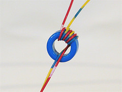
Of course, the part over which most builders will stumble is the transformer. I used an Amidon EA-77-188 core, because I had it at hand, and it was the smallest core I had. I should say that this core is still at least five times larger than required! So feel free to use the smallest ferrite double-E core you can find, or any other ferrite core that offers a closed loop and the possibility of assembling it with an air gap. But then you will have to redo the math!

The main winding has 18 turns, and I wound it with 7 strands of #30 enameled wire twisted together, simply because there is room enough to do so. But this thick wire bundle is huge overkill, like the whole transformer is! The feedback winding  was wound with a single strand of that same #30 wire, and it has just three turns. The phasing is like shown in the diagram, of course. If you get the phasing wrong, the circuit won't work and the transistor will get warm.

I used masking tape to hold the windings in place on the bobbin. No special insulation is required, because the voltages are so low that the enamel on the wire is insulation enough.

Now comes a very important step: This transformer is airgapped. The two core halves need to be separated by a distance of 0.1mm. I simply stuck little pieces of masking tape on the three legs of one core half, taking advantage of the fact that my masking tape is just the right thickness! Then I assembled the core, wrapping masking tape around it to hold it together.

If you have to use a different ferrite core, you can use my transformers and coils article to learn how to design your transformer. The turns ratio will of course remain 6:1, but the absolute number of turns will change in inverse proportion  to the core's cross section. You can look up the data of my core on Amidon's or Bytemark's websites, compare that to the data for your core, and go from there. After calculating the turns numbers, you have to calculate the required air gap to obtain an inductance of the main winding of about 40µH.

The transistor I used, the 2SC1226A, is a pretty old part and may no longer be available. I have a bunch of them, so I used it. It has a soft, thin copper tab which can easily be cut off, which is an advantage in this circuit, because it allows saving some space! The transistor works cold, so it doesn't really need the tab! If you have to use another transistor instead, feel free, but look for one which has the proper characteristics: It should have a breakdown voltage of about 40V, a maximum continuous current of about 3A, be reasonably fast (mine is very fast, having an Ft of 150MHz!), it should have good saturation characteristics, and it should have a reasonably high hfe (at least 30, ideally about 100) at a current of 1A.

Any different transistor will most likely require a change in the value of R1, to set the proper power level for the LEDs. You can experimentally determine that resistor value, by placing a milliamperemeter in series with the LED string, and selecting the resistor for 20mA in the LEDs. By the way, if you want to build this circuit for an alkaline cell instead of a NiMH cell, the resistor should be a bit higher. D2 is a Schottky rectifier. A non-Schottky ultrafast diode could be used too, but the Schottky is better. D1 instead is any plain simple silicon diode.

If your power switch doesn't have very low resistance, it might cause a significant loss in this low voltage circuit! If that happens, you could instead place the power switch in series with R1, leaving the rest of the circuit permanently energized. That will cost almost no lost battery power, because the only current drain when off will be the leakage through the parts, which should be in the microampere range. But if you place the switch at R1, you should also place a 1 megaohm resistor (or almost any other high value) in parallel with D1, to make sure that the transistor really does stay fully off when it should!
Source: Humo Ludens

Handy Pen Torch

This easy to construct “Handy pen torch” electronic circuit and low component count, uses two power white LEDs for lighting. Low volt (4.8V dc) supply available from the built in rechargeable Ni-Cd battery pack is first converted into two channel (independent) constant current sources by two pieces of the renowned precision adjustable shunt regulator chip LM334 (IC1 and IC2). Around 25mA at 3.6 volt dc is available at the output of these ICs.

This regulated dc supply is used to drive two power white LEDs D4 and D6. Resistors R3 and R5 limits the output current (and hence the light output) of IC1 and IC2 circuits respectively. Besides these components, one red color LED (D2) is included in the main circuit which works as a battery charging supply input indicator. Resistor R1 limits the operating current of this LED.

Pen Torch Electronic Circuit Schematic
Circuit Project: Handy Pen Torch circuit

Diode D1 works as an input polarity guard cum reverse current flow preventer. Capacitor C1 is a simple buffer for circuit stabilization. After succesful construction, preferably on a small piece of general purpose PCB, enclose the whole circuit in a suitable and attractive pen torch cabinet. If necessary, drill suitable holes in the cabinet to attatch the dc socket, on/off switch and the input indicator etc. In prototype,commonly available 4.8 volt/500mah Ni-Cd battery pack (for cordless telephones) is used.

One very simple but reliable ac mains powered battery charger circuit for the handy pen torch is also included here. Basically the pen torch circuit is a constant current charger wired around Transistor T1 (BC636), powered by a 12v/350mA step down transformer and associated componentsD1, D2 and C1.

AC mains powered battery charger for the pen torch
Circuit Project: Handy Pen Torch circuit
Unregulated 12 volt dc available from the input power convereter circuit, comprising step down transformer(TRF), rectifier diodes (D1,D2) and filter capacitor (C1), is fed to T1 through a current limiting resistor R1. Grounded base PNP transistor T1 here works as a constant current generator. With 22 ohm resistor for R1, the charging current available at the output of the charger is near 50mA.

Red LED (D3) provides a fixed voltage reference to the base of T1, with the help of resistor R2. (During charging process, Diode D1 in the main circuit prevent reverse current flow from the battery pack when charging input supply is absent.) After construction of the pen torch circuit, fit the assembled unit inside a small plastic enclosure for safety and convenience.

Circuit Source: DIY Electronics Projects

Automobile White LED Light

Without any dedicated buck converter/white LED driver IC, you can safely drive many standard Hi-efficient white LED modules using the battery power available in automobiles. Here is a safe and simple white LED driver designed for 12V automobiles.

Auto White LED Circuit Schematic
Circuit Project: Automobile White LED Light

In the Automobile White LED Light circuit, fixed voltage regulator IC1 (7805) provides a steady voltage of 5V across C2. Resistors R1 limits the current flow through the white LED D1 (3v6/350mA) with the help of transistor T1 (and T2), ie components R1, T1 (and T2) provide a constant current to D1. Use a good heat sink for T1. This LED unit gives a constant light output for input voltages ranging from 8 to 18 volts!

Circuit Source: DIY Electronics Projects

Portable Solar Lantern

This portable solar lantern circuit uses 6 volt/5 watt solar panels are now widely available. With the help of such a photo-voltaic panel we can construct an economical, simple but efficient and truly portable solar lantern unit. Next important component required is a high power (1watt) white LED module.

When solar panel is well exposed to sunlight, about 9 volt dc available from the panel can be used to recharge a 4.8 volt /600 mAh rated Ni-Cd batterypack. Here red LED (D2) functions as a charging process indicator with the help of resistor R1. Resistor R2 regulates the charging current flow to near 150mA.

Solar Lantern Circuit Schematic
Circuit Project: Portable Solar Lantern

Assuming a 4-5 hour sunlit day, the solar panel (150mA current set by the charge controller resistor R2) will pump about 600 – 750 mAh into the battery pack. When power switch S1 is turned on, dc supply from the Ni-Cd battery pack is extended to the white LED (D3). Resistor R3 determines the LED current. Capacitor C1 works as a buffer.

Note: After construction, slightly change the values of R1,R2 and R3 up/down by trial&error method, if necessary.

16 Stage Bi-Directional LED Sequencer

The bi-directional sequencer uses a 4 bit binary up/down counter (CD4516) and two "1 of 8 line decoders"74HC138 or 74HCT138) to generate the popular "Night Rider" display. A Schmitt Trigger oscillator provides the clock signal for the counter and the rate can be adjusted with the 500K pot. Two additional Schmitt Trigger inverters are used as a SET/RESET latch to control the counting direction (up or down).

Be sure to use the 74HC14 and not the 74HCT14, the 74HCT14 may not work due to the low TTL input trigger level. When the highest count is reached (1111) the low output at pin 7 sets the latch so that the UP/DOWN input to the counter goes low and causes the counter to begin decrementing. When the lowest count is reached (0000) the latch is reset (high) so that the counter will begin incrementing on the next rising clock edge.

Circuit Project: 16 Stage Bi-Directional LED Sequencer

The three lowest counter bits (Q0, Q1, Q2) are connected to both decoders in parallel and the highest bit Q3 is used to select the appropriate decoder. The circuit can be used to drive 12 volt/25 watt lamps with the addition of two transistors per lamp as shown below in the section below titled "Interfacing 5 volt CMOS to 12 volt loads".

Sound Activated Lights

This diy sound activated lights circuit turns a lamp ON for a short duration when the dog barks (or a relatively strong sound) giving an impression that the occupants have been alerted. The condenser microphone fitted in a place to monitor sound and generates AC signals, which pass through DC blocking capacitor C1 to the base of transistor BC549 (T1). Transistor T1 along with transistor T2 amplifies the sound signals and provides current pulses from the collector of T2. When sound is produced in front of the condenser mic, triac1 (BT136) fires, activates lights and the bulb (B1) glows for about two minutes.
 Assemble the sound activated lights circuit on a general purpose PCB (circuit board) and enclose in a plastic cabinet. Power to the sound activated switch circuit can be derived from a 12V, 500mA step-down transformer with rectifier and smoothing capacitor. Solder the triac ensuring sufficient spacing between the pins to avoid short circuit. Fix the unit in the dog’s cage or close to the sound monitoring spot, with the lamp inside or outside as desired. Connect the microphone to the sount activated lights circuit using a short length of shielded wire. Enclose the microphone in a tube to increase its sensitivity.

Caution. Since the sound activated lights uses 230V AC, many of its points are at AC mains voltage. It could give you lethal shock if you are not careful. So if you don’t know much about working with line voltages, do not attempt to construct this circuit. We will not be responsible for any kind of resulting loss or damage.

40 LED Bicycle Light

The 555 circuit below is a flashing bicycle light powered with four C,D or AA cells (6 volts). Two sets of 20 LEDs will alternately flash at approximately 4.7 cycles per second using RC values shown (4.7K for R1, 150K for R2 and a 1uF capacitor). Time intervals for the two lamps are about 107 milliseconds (T1, upper LEDs) and 104 milliseconds (T2 lower LEDs). Two transistors are used to provide additional current beyond the 200 mA limit of the 555 timer. A single LED is placed in series with the base of the PNP transistor so that the lower 20 LEDs turn off when the 555 output goes high during the T1 time interval. The high output level of the 555 timer is 1.7 volts less than the supply voltage.

Circuit  Project: 40 LED Bicycle Light

Adding the LED increases the forward voltage required for the PNP transistor to about 2.7 volts so that the 1.7 volt difference from supply to the output is insufficient to turn on the transistor. Each LED is supplied with about 20mA of current for a total of 220mA. The circuit should work with additional LEDs up to about 40 for each group, or 81 total. The circuit will also work with fewer LEDs so it could be assembled and tested with just 5 LEDs (two groups of two plus one) before adding the others.

Circuit Source: DIY Electronics Projects

6-Channel Running Light

The circuit of the running light comprises two integrated circuits (ICs), a resistor, a capacitor and seven light-emitting diodes (LEDs), Decade scaler IC2 ensures that the LEDs light sequentially. The rate at which this happens is determined by the clock at pin 14. The clock is generated by IC1, which is arranged as an astable multivibrator. Its frequency is determined by R1-C1.
6-Channel Running Light
6-Channel Running Light Circuit Diagram
The touch switch, consisting of two small metal disks is optional. When switch S1 is in position ‘off’, the circuit may be actuated by the touch switch. By the way, this enables the circuit to be used as an electronic die (in which case the LEDs have to be numbered from 1 to 6). The running light is powered by a 9 V battery or mains adapter. It draws a current not exceeding 20 mA.

Author: L. v/d Heeden
Copyright: Elektor Electronics 1998

Solar Powered Animal Scarer

Here is a solar powered Flasher to scare away the nocturnal animals like bats and cats from the farm yard or premises of the house. The brilliant multicolored flashes confuse these animals and they avoid the hostile situation. It is fully automatic, turns on in the evening and turns off in the morning.

The circuit has an LDR controlled oscillator built around the Binary counter IC CD 4060.The functioning of the IC is controlled through its reset pin 12. During day time, LDR conducts and keeps the reset pin of IC high so that it remains dormant. During night, LDR cease to conduct and the reset pin will be grounded through VR1. This triggers the IC and it stats oscillating using the components C1 and VR2. Output pins 7, 5 and 4 are used to power the LEDs strings.

VR1 adjusts the sensitivity of LDR and VR2, the flashing rate of LEDs. High bright Red, Blue and White LEDs are used in the circuit to give brilliant flashes. Red LEDs flash very fast, followed by blue and then White. White LEDs remains on for few seconds and provide light to a confined area. More LEDs can be added in the strings if desired. The circuit can also function with 12 volt DC.

Animal Repellent Circuit Diagram

Solar Powered Animal Scarer

The circuit uses a solar powered battery power supply. During daytime, battery charges through R1 and D1.Green LED indicates the charging mode. During night time current from the solar cell decreases and D1 reverse biases. At the same time D2 forward biases to provide power to the circuit. Resistor R1 restricts the charging current and the high value capacitor C1 is a buffer for current.

Animal Scarer Solar Power Supply

Solar Powered Animal Scarer


Simple Emergency Light

This is an automatic emergency lamp with day light sensing, means it senses darkness/night and turns ON automatically. Similarly it senses day light and turns OFF automatically. A simple emergency lamp which does not require any special equipment; even a multimeter to assemble and use. Any individual who can do a good quality soldering must be able to build this circuit successfully.

This can be easily accommodated in the defunct two 6 watt tube National Emergency Lamp or any PL tube type emergency lamp. The difference will be in the working; it will work non stop for more than 8 hours. Deep discharge is taken care by the LED characteristic and over charge protection is taken care by the fixed voltage regulator.This uses a simple 3Pin fixed regulator which has a built in current limiting circuit.

Simple Emergency Light Circuit Diagram:
Circuit Project: Simple Emergency Light Circuit

The only required adjustment is the preset which has to be set to ensure the LEDs just light up (it should be left at that position). The 5mm LDR is just mounted on top of the emergency light as shown in the photograph. LDR is used to avoid it lighting up during day time or when the room lights are ON. 2 LEDs are used in series; the dropping resistance is avoided and 2 LEDs light up with current that is required for a single LED,  by which energy is saved to a great extent.

This particular circuit has been kept so simple for people who has limited access to components or in other words this is an emergency light that you can build with minimum components. In addition to circuit diagram, He has shared photographs of the prototype he made in National emergency light and a PCB design.

Flashing-LED Battery-Status Indicator Circuit

A Battery-status Indicator circuit can be useful, mainly to monitor portable Test-gear instruments and similar devices. LED D1 flashes to attire the user's attention, signaling that the circuit is running, so it will not be left on by mistake. The circuit generates about two LED flashes per second, but the mean current drawing will be about 200µA. Transistors Q1 and Q2 are wired as an uncommon complementary astable multivibrator: both are off 99% of the time, saturating only when the LED illuminates, thus contributing to keep very low current consumption.
Circuit operation:

The circuit will work with battery supply voltages in the 5 - 12V range and the LED flashing can be stopped at the desired battery voltage (comprised in the 4.8 - 9V value) by adjusting Trimmer R4. This range can be modified by changing R3 and/or R4 value slightly. When the battery voltage approaches the exhausting value, the LED flashing frequency will fall suddenly to alert the user. Obviously, when the battery voltage has fallen below this value, the LED will remain permanently off. To keep stable the exhausting voltage value, diode D1 was added to compensate Q1 Base-Emitter junction changes in temperature. The use of a Schottky-barrier device (e.g. BAT46, 1N5819 and the like) for D1 is mandatory: the circuit will not work if a common silicon diode like the 1N4148 is used in its place.

Circuit diagram:

Flashing-LED Battery-Status Indicator Circuit


R1 = 220R - 1/4W Resistor
R2 = 120K - 1/4W Resistor
R3 = 5.6K - 1/4W Resistor
R4 = 5K - 1/2W Trimmer Cermet
R5 = 33K - 1/4W Resistor
R6 = 680K - 1/4W Resistor
R7 = 220R - 1/4W Resistor
R8 = 100K - 1/4W Resistor
R9 = 180R - 1/4W Resistor
C1 = 4.7uF - 25V Electrolytic Capacitors
C2 = 4.7uF - 25V Electrolytic Capacitors
Q1 = BC547 - 45V 100mA NPN Transistor
Q2 = BC557 - 45V 100mA PNP Transistor
B1 = 5V to 12V Battery supply
D1 = BAT46 - 100V 150mA Schottky-barrier Diode
D2 = LED - Red 5mm.

Note:
  • Mean current drawing of the circuit can be reduced further on by raising R1, R7 and R9 values.

Two-Cell LED Torch

It sometimes comes as a bit of a shock the first time you need to replace the batteries in an LED torch and find that they are not the usual supermarket grade alkaline batteries but in fact expensive Lithium cells. The torch may have been a give away at an advertising promo but now you discover that the cost of a replacement battery is more than the torch is worth. Before you consign the torch to the waste bin take a look at this circuit. It uses a classic two-transistor astable multivibrator configuration to drive the LEDs via a transformer from two standard 1.5 V alkaline batteries.

The operating principle of the multivibrator has been well documented and with the components specified here it produces a square wave output with a frequency of around 800 Hz. This signal is used to drive a small transformer with its output across two LEDs connected in series. Conrad Electronics supplied the transformer used in the original circuit. The windings have a 1:5 ratio. The complete specification is available on the (German) company website at www.conrad.de part no. 516236. It isn’t essential to use the same transformer so any similar model with the same specification will be acceptable.
Two-Cell LED Torch

The LEDs are driven by an alternating voltage and they will only conduct in the half of the waveform when they are forward biased. Try reversing both LEDs to see if they light more brightly. Make sure that the transformer is fitted correctly; use an ohmmeter to check the resistance of the primary and secondary windings if you are unsure which is which. The load impedance for the left hand transistor is formed by L in series with the 1N4002 diode. The inductance of L isn’t critical and can be reduced to 3.3 mH if necessary. The impedance of the transformer secondary winding ensures that a resistor is not required in series with the LEDs.

Unlike filament type light sources, white LEDs are manufactured with a built-in reflector that directs the light forward so an additional external reflector or lens glass is not required. The LEDs can be mounted so that both beams point at the same spot or they can be angled to give a wider area of illumination depending on your needs. Current consumption of the circuit is approximately 50 mA and the design is even capable of producing a useful light output when the battery voltage has fallen to 1 V. The circuit can be powered either by two AAA or AA size alkaline cells connected in series or alternatively with two rechargeable NiMH cells.