Tri-Waveform Generator

The Tri-Waveform Generator can be used for a number of different uses. The one that I use it for is a signal generator to test circuits. The frequency range is 20 to 20khz. and can be adjusted by R1. The duty cycle or the time that the waveform is high and the time that the waveform is low can be adjusted by R4. The purpose of R2 and R3 are to clean up any distortion on the sine wave output. To do this you must hook up the sine wave output to and oscilloscope and adjust R2 & R3 to make the sine wave as accurate as possible.

Audible Logic Probe

When testing circuits with a logic probe, it is sometimes difficult to watch the LEDS on the probe to determine the logic state. With this probe the logic states are audible. This probe is designed for TTL circuits only but could be modified for CMOS. The way it works is as follows. The 5 volt power source will be the circuit under test. Clip the ground input of the probe to the ground of the circuit being tested. The other input lead is used to probe the different chips of the circuit being tested. Any input greater then 2 volts will be high and output a high tone through the speaker. Any input less then .8 volts will be low and produce a low tone through the speaker.

Audible Logic Probe circuit diagram

Drill Speed Regulator

A mini-drill machine is always needed in drilling the printed circuit board. It is usually powered by batteries that limit the drill’s capacity.Using a power supply adaptor with a speed regulator like the one featured here can certainly improve the performance of the drill.

The speed regulator can maintain the speed of the drill no matter what load is encountered by the drill.Potentiometer P2 controls the speed of the mini-drill. P1 sets the maximum voltage allowed by the mini-drill.

Drill speed regulator circuit schematic
Circuit Project: Drill speed regulator circuit

Caution! Danger of electrocution!
Extreme shock hazard. You are working a line voltage of 220 Volts AC.

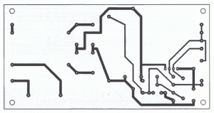
Mini-drill speed regulator PCB
Circuit Project: Drill speed regulator circuit

Geiger Counter Uses Cockroft-Walton Multiplier

The recent tsunami in Japan and the on-going calamity with the Fukushima nuclear power plant has apparently greatly increased sales of radiation meters, not only in Japan but elsewhere around the world. This device will allow an estimation of the level of radioactivity, being sensitive enough for background radiation monitoring or to provide an estimation of the level of radioactivity from sample objects such as Thorium gas mantles in LPG lamps. The circuit is compatible with several Geiger Muller tubes and three types of indication are provided: the good old-fashioned audible click with each discharge, a flashing LED or an analog meter providing a rough average of radiation levels.

Geiger Counter Uses Cockroft-Walton Multiplier
A normal background count in New Zealand with the smaller GM LND712 tube is around 30 counts per minute, while the larger and more-sensitive LND7312 pancake tube will count about four times this figure. Both GM tubes will detect alpha, beta and gamma radiation. Unless the tube is “filtered”, there is no way of knowing just what type of radiation is being detected, although a rough guess can be made. Alpha particles will be stopped by placing a sheet of paper between the tube and the source, Beta particles (electrons) will be stopped with a few layers of aluminium foil and the more lively Gamma rays will need a layer of lead.

The circuit provides a regulated 500V supply for the Geiger Muller tube. This voltage places the tube into its linear operating mode so that a discharge inside the tube will occur when a particle enters through the mica window of the tube and causes the gas to ionise. The very short pulse produced is stretched and used to signal that a discharge has occurred. The power supply consists of an oscillator and small transistor driving the 6V secondary of a 240VAC mains transformer. The stepped up output of the transformer is fed to a Cockroft-Walton voltage multiplier consisting of diodes D3-D7 and the associated 47nF 630V metallised polyester capacitors.

IC1 is a 40106 Schmitt trigger inverter and IC1a is connected as an oscillator running at several hundred hertz. This is buffered by IC1b and fed to the base of NPN transistor Q1 which then drives the abovementioned transformer. IC1c acts as an error amplifier to regulate the high voltage fed to the GM tube. A portion of the DC voltage produced at the junction of diodes D4 & D5 is monitored by a voltage divider consisting of the 4.7MO and 47kO resistors, in combination with trimpot VR1. When the voltage from D5 is below the positive threshold of IC1c, its output will be high and IC1a will be able to oscillate. Hence, the oscillator will pulse on and off, to maintain the 500V set by VR1.

Each time there is a discharge in the GM tube, the resultant current triggers the BT149 SCR which discharges the associated 100nF capacitor and thereby acts as a pulse stretcher to drive the three remaining inverters in IC1. These in turn drive a high-brightness red LED (LED1), a piezo transducer and an analog metering circuit which is based on an old VU meter movement with a scale graduated in counts/minute. The current drain of the circuit is 10mA and a small 9V battery should run the counter for many hours. Warning: do not touch the window of the GM tube. These are very fragile and made of very thin mica, to allow the low-energy alpha particles to pass through. With the LND 712, 200 counts per minute is roughly equivalent to 0.3 micro-seiverts.

Power Diode For Solar Power Systems

Apart from the sun, solar power systems cannot work without a reflow protection diode between the solar panel and the energy store. When current flows into the store, there is a potential drop across the diode which must be written off as a loss in energy. In the case of a Schottky diode, this is not less than 0.28 V at nominal current levels, but will rise with higher ones. It is clear that it is advantageous to keep the energy loss as small as possible and this may be achieved with external circuitry as shown in the diagram. The circuit is essentially an electronic switch consisting of a high precision operational amplifier, IC1a, a Type OP295 from Analog Devices, and a MOSFET, T1.

This arrangement has the advantages over a Schottky diode that it has a lower threshold voltage and the lost energy is not dissipated as heat so that only a small heat sink is needed. When the potential at the non-inverting input of the op amp, which is configured as a comparator, rises above that at the inverting input, the output switches to the operating voltage. The transistor then comes on, whereupon light-emitting diode LD1 lights. Diode D3 clamps the inputs of IC1a so that the peak input voltage cannot be greater than half the threshold voltage, provided the values of R3 and R4 are equal.

Power Diode For Solar Power Systems
The op amp provides very high small-signal amplification, a small offset voltage, and consequent fast switching. The MOSFET changes from on to off state and vice versa at drain -source voltages in the microvolt range. In the quiescent state, when UDS is 0 V, the transistor is on, so that LD1 lights. The operating voltage (C–A) may be between 5 V (the minimum supply for the op amp and the input control potential, UGS, of the transistor) and 36 V (twice the zener voltage of D1). Zener diode D1 protects the MOSFET against excessive voltages (greater than ±20 V). Diode D3 and resistors R3 and R4 halve the potential across the inputs of the op amp.

This ensures that operation with reversed or open terminals is harmless. The substrate diode of the MOSFET is of no consequence since it does not become forward biased as long as the forward voltage, USD, of the transistor is held very low. The on -resistance, RSD(on), of the transistor is only 8 mΩ and the transistor can handle currents of up to 75 A. When the nominal current is 10 A, the drop across the on-resistance is 80 mV, resulting in an energy loss of 0.8W. This is low enough for a SUB type with a TO263-SMD case to be used without heat sink. When the current is 50 A, however, it is advisable to use a SUP type with a TO220 case and a heat sink since the transistor is then dissipating 12.5 W.

Even then, the voltage drop, USD = 0.32 V is significantly lower than that across a Schottky diode in the same circumstances. Moreover, owing to the high precision of IC1a, a number of transistors may be used in parallel. The circuit proper draws a current of 150 µA when only one of the op amps in the OP295 is used. An even lower current is drawn by the alternative Type MAX478 from Maxim. However, the differences between these two types are only relevant in the low current and voltage ranges. Both have rail-to-rail outputs that set the control voltage accurately even at very low operating voltages.

This is important since the switch-on resistance of MOSFETs is not constant: t drops significantly with increasing gate potentials and decreasing temperature. A experimental circuit may use an LM358 op amp and a Type BUZ10 transistors, but these components do not give the excellent results just described.

Opamp With Hysteresis

At first glance, the circuit in the diagram does not look out of the ordinary, and yet, it is. This is because it combines two characteristics that are usually assumed to be incompatible: hysteresis and a high input impedance. In a standard op amp circuit, this is, indeed, true, because the creation of hysteresis is normally achieved by positive feedback to the +ve input of the op amp. Unfortunately, the requisite resistance network causes a drastic deterioration of the original high input impedance of the op amp. So, when a high input impedance and hysteresis are wanted, the solution is to obtain the needed positive feedback by coupling the resistor network not to the +ve input but to the offset correction pin.
Opamp With Hysteresis

When this done, the hysteresis so obtained is calculated from Uh = 1.2/R4Uo, where Uh is the hysteresis voltage and Uo is the output voltage of the op amp, both in volts The value of R4 must be in kΩ. The level of Uo depends, of course, on the load.

Cat And Dog Repellent

The electronic dog repellent circuit diagram below is a high output ultrasonic transmitter which is primarily intended to act as a dog and cat repeller, which can be used individuals to act as a deterrent against some animals. It should NOT be relied upon as a defence against aggressive dogs but it may help distract them or encourage them to go away and do not consider this as an electronic pest repeller. The ultrasonic dog repellant uses a standard 555 timer IC1 set up as an oscillator using a single RC network to give a 40 kHz square wave with equal mark/space ratio.

This frequency is above the hearing threshold for humans but is known to be irritating frequency for dog and cats. Since the maximum current that a 555 timer can supply is 200mA an amplifier stage was required so a high-power H-bridge network was devised, formed by 4 transistors TR1 to TR4. A second timer IC2 forms a buffer amplifier that feeds one input of the H-bridge driver, with an inverted waveform to that of IC1 output being fed to the opposite input of the H-bridge.

Circuit diagram:Cat And Dog Repellent
Cat And Dog Repellent Circuit Diagram

This means that conduction occurs through the complementary pairs of TR1/TR4 and TR2/TR3 on alternate marks and spaces, effectively doubling the voltage across the ultrasonic transducer, LS1. This is optimised to generate a high output at ultrasonic frequencies. This configuration was tested by decreasing the frequency of the oscillator to an audible level and replacing the ultrasonic transducer with a loudspeaker; the results were astounding. If the dog repellent circuit was fed by a bench power supply rather than a battery that restrict the available current, the output reached 110dB with 4A running through the speaker which is plenty loud enough!

The Dog and Cat repellant was activated using a normal open switch S1 to control the current consumption, but many forms of automatic switching could be used such as pressure sensitive mats, light beams or PIR sensors. Thus it could be utilise as part of a dog or cat deterrent system to help prevent unwanted damage to gardens or flowerbeds, or a battery powered version can be carried for portable use. Consider also using a lead-acid battery if desired, and a single chip version could be built using the 556 dual timer IC to save space and improve battery life.