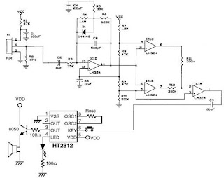
A very simple pir motion detector circuit can be designed using this diagram .This pir motion detector circuit project use a PIR sensor , operational amplifiers a sound generator circuit and some others common electronic components .The op-amp IC1D shapes the frequency response to amplify those frequencies produced when motion is detected and rejects all others, such as those due to noise or slow temperature changes.As motion is detected, the voltage at the output will change and trigger either IC1C or IC1B.The op-amps IC1A, IC1B and IC1C are configured as voltage comparators.
When IC1D outputs a voltage lower than 1.41V, it will force pin 2 of IC1 high.When IC1D outputs a voltage higher than 1.67V, it forces pin 8 and pin 2 of IC1 to go high. A high in with one of these cases causes the output to go low and allows C9 to discharge through IC1A. The discharging of C9 will pull pin 6 of IC2 low and trigger the sound generator.The Passive Infrared Sensor (PIR) used in this alarm circuit can be LHI-954 , KDS245 or other similar type .As sound generator you can use a HT2810 or HT2812 sound generator integrated circuit .This motion detector alarm circuit requires two DC voltage 5 volts for almost all power connections and 9 volts for the sound generator circuit .
When IC1D outputs a voltage lower than 1.41V, it will force pin 2 of IC1 high.When IC1D outputs a voltage higher than 1.67V, it forces pin 8 and pin 2 of IC1 to go high. A high in with one of these cases causes the output to go low and allows C9 to discharge through IC1A. The discharging of C9 will pull pin 6 of IC2 low and trigger the sound generator.The Passive Infrared Sensor (PIR) used in this alarm circuit can be LHI-954 , KDS245 or other similar type .As sound generator you can use a HT2810 or HT2812 sound generator integrated circuit .This motion detector alarm circuit requires two DC voltage 5 volts for almost all power connections and 9 volts for the sound generator circuit .

